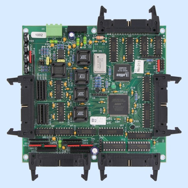
XmPga01 - Programmable inputs and outputs board
- can be connected to XBus interface of ConTeK control system
- 16 byte address space
- 16 digital inputs
- selectable signal level for groups of 4 inputs (5V, 24V)
- 32 digital outputs
- 16 outputs TTL
- 16 outputs TTL or with transistor switches
- oscillator for resolver excitation
- selectable frequency 2, 5, 10, 20kHz
- up to 4 resolver inputs
- resolution 12 bit
- incremental and absolute mode
- adjustable input sensitivity
- all inputs and outputs can be processed by FPGA
- variable function, defined by FPGA project
- 5120 bytes general purpose RAM
- frequency 20MHz
Description
XmPga01 board is suitable for application, where rotating or linear resolvers must be processed or where digital inputs and outputs must be specially processed. Board can realize e.g. fast control of stepper motor with MSm01, generating of digital signal sequences, accurate measurement of frequency or duty cycle, impulse counting etc.
Board can be connected to XBus interface of ConTeK control system.
Core of XmPga01 is FPGA - programable array from Altera, which provides processing of all inputs, outputs and resolver decoders. FPGA function is defined by configuration file, which is loaded from control unit through XBus interface.
Resolver inputs allows connecting and processing up to four revolving or linear resolvers. Inputs consist of amplifier with gain, which can be set by inserting resitor network into socket. Gain is common for two resolver inputs. Difference between input signals of one resolver can be compensated by resistor trimmers.
Common sinus oscillator with selectable frequency provides excitation for all resolvers.
Each digital input has resistance T-element. This allows setting of input signal level simply by inserting resitor network into socket. Resistor network is common for group of four signals. Input signals are connected by 34 wire flat cable.
All digital outputs has TTL buffers. Moreover 8 or 16 outputs can be equipped with transistor switches. Output signals are connected by two 34 wire flat cables.
Technical parameters
- Power supply voltage: 5V from XBus
- Current consumption: 150mA (with disconnected resolvers)
- Operating temperature: 0-70°C
- Interface
- Bus: ConTeK XBus, 34 pins
- Addressing: can be set between 00h-F0h in 16-byte steps
- IRQ: depends on FPGA project
- Digital inputs
- Number of inputs: 16
- Input voltage: can be set 24V or 5V independently for groups of 4 inputs
- Level L: max. 8V for 24V range, 1.6V for 5V range
- Level H: min. 16V for 24V range, 3.3V for 5V range
- Digital outputs
- Number of outputs: 16 + 16
- TTL outputs
- Output voltage: 5V
- Level L: max. 0.33V, 6mA
- Level H: min. 3.7V, -6mA
- Frequency: depends on FPGA project
- Transistor outputs
- Output voltage: max. 35V
- Output current: max. 100mA
- Voltage drop: 1.5V
- Frequency: max. 100kHz
- Resolver inputs
- Number of inputs: 0 - 4
- Excitation voltage: 2.2Vef
- Excitation frequency: selectable 2, 5, 10, 20kHz
- Input voltage: 2Vef, adjustable
- Speed: max. 30000 rpm